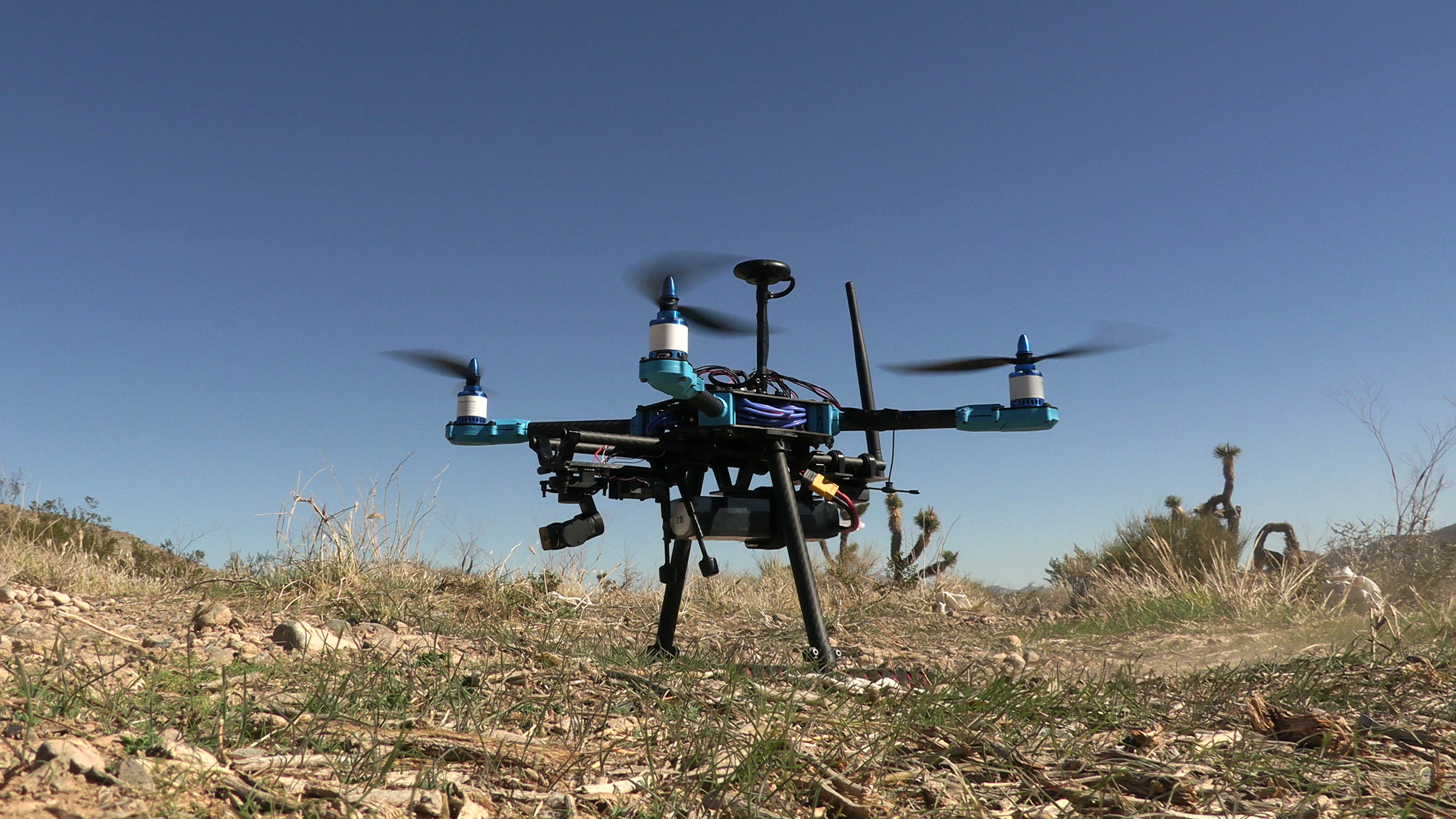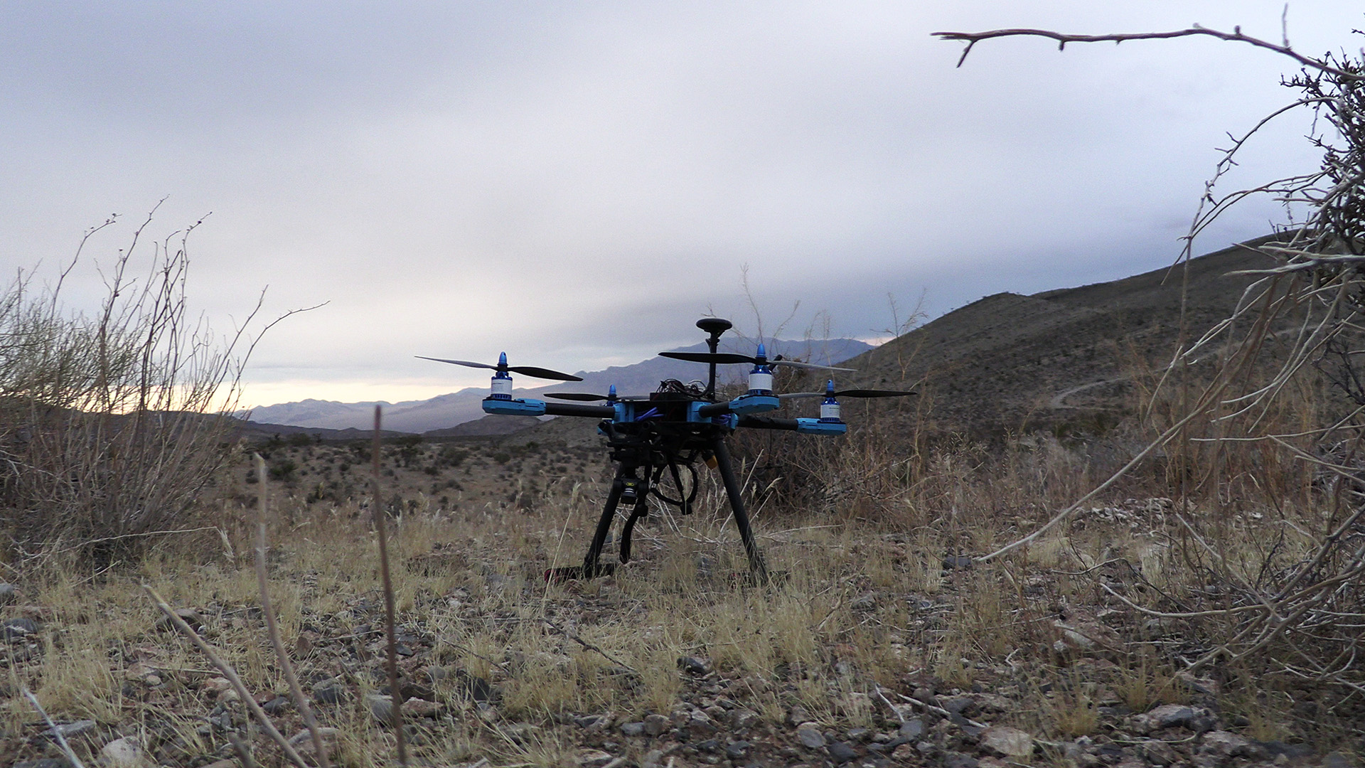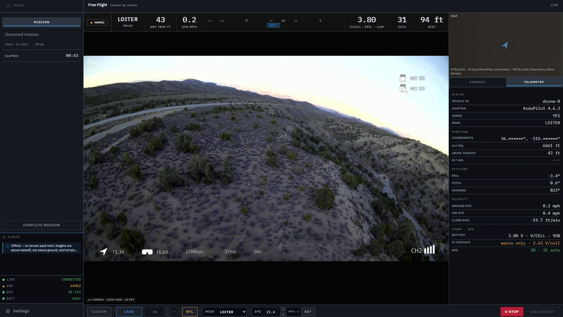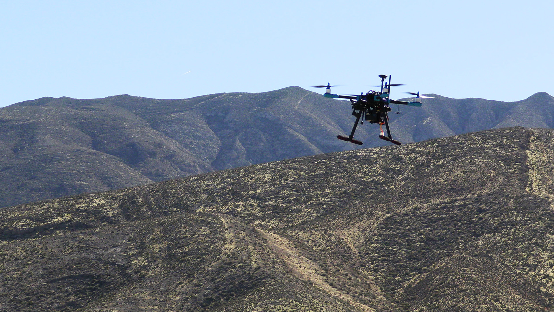
A flight controller is the onboard computer that runs an aircraft’s flight software. The autopilot is the software and control system using that computer to manage the flight. A ground control station gives the person on the ground a way to see what the aircraft is reporting, change supported settings and send instructions.
That is a useful starting point, although the names aren’t always used so neatly. A hardware listing might call a flight controller an autopilot. Someone discussing software might use the same word for ArduPilot or PX4. The controller in the pilot’s hands introduces another meaning of “controller” before you’ve even connected a cable.
Picture a drone on a workbench, with a radio transmitter beside it and a laptop connected over USB. You open the ground station and the aircraft’s readings appear. All three pieces are involved, but they have different jobs. The laptop isn’t the computer that keeps the drone level. The transmitter isn’t running the mission planner. The small board inside the aircraft is doing a lot of work you won’t see directly.
Following those jobs through a flight makes the terminology much easier to live with.
Three jobs behind the names
For this article, we’ll use the terms this way:
| Part | Main job |
|---|---|
| Flight controller | Provide the onboard hardware that connects flight software, sensors and control outputs |
| Autopilot software | Estimate the aircraft’s state and run the control, navigation and flight behavior supported by the setup |
| Ground control station | Give the operator an interface for aircraft information, configuration, commands and supported planning or review tools |
The flight controller and autopilot software work together onboard. A ground station is another part of the system, connected to them. The radio transmitter and receiver provide a typical route for the pilot’s stick and switch inputs.
These are roles rather than a guarantee about the number of boxes. A handheld unit can combine sticks, a screen, ground station software and a radio link. Sensors may be built into a flight controller or connected separately. Combining the packaging doesn’t remove the different jobs inside it.
The flight controller lives with the aircraft
The flight controller, often shortened to FC, is a physical computer carried by the drone. In a typical multicopter setup, it includes a processor and onboard sensors, with connections for other equipment. PX4’s basic concepts guide describes the controller as the hardware on which its flight software runs, connected to the sensors and actuators used to control the vehicle.
Some sensors sit on the board. Others can be separate modules, such as a satellite-navigation receiver or an external compass. A receiver for the pilot’s radio, a telemetry connection and motor-control outputs also need somewhere to connect. Looking at a wiring diagram is often the moment when the controller’s central role becomes obvious.
There is an electrical distinction worth keeping in mind. The flight controller sends control signals. On a typical electric multicopter, electronic speed controllers, or ESCs, handle the electrical drive to the motors. ArduPilot’s typical autopilot wiring guide shows the sensor, RC and motor or servo connections around the board.
Asking for a change in motor output and supplying the power to make it happen are separate jobs. You can have a perfectly good connection to the flight controller while still having a problem elsewhere in that chain.
The autopilot is doing more than following a route
The flight controller needs software to turn its hardware into a flight system. You’ll often see that onboard software called firmware, because it is installed on the device. ArduPilot and PX4 are familiar examples of autopilot software. The term flight stack is also used when discussing the collection of software involved.
Its work extends well beyond waypoint missions. The software can read sensors, estimate movement and orientation, interpret inputs, run controllers, manage flight modes and report information to other systems. Which parts are active depends on the aircraft, software and configuration.
An autopilot can therefore be working throughout a flight while a person is actively flying with the sticks. Automatic stabilization and automatic route following are different levels of assistance. Having autopilot software onboard doesn’t mean every flight is an unattended mission.
Flight modes make that distinction concrete. ArduCopter’s flight mode guide separates modes such as Stabilize, Alt Hold, Loiter, Guided and Auto. They differ in what the pilot controls, what the aircraft handles and what information the system needs. Some require a valid position estimate; others don’t.
The same hardware can behave quite differently after a mode change. If you want to understand who is asking the aircraft to do what, the reported mode belongs alongside the physical equipment and software names.
From a sensor reading to a motor adjustment
Imagine a multicopter holding position while a gust disturbs it. Keeping it where it was involves more than receiving another position from GPS.
The system gathers measurements from its available sensors. Gyroscopes measure rotation rates; accelerometers measure acceleration. Other measurements can come from a compass, barometer, satellite-navigation receiver or additional sensors. The autopilot uses an estimator to combine information into its best available account of the aircraft’s state.
That state includes things such as attitude, meaning the aircraft’s orientation, and its estimated position and movement. A controller compares the relevant estimate with a desired value and works out an appropriate response. The outputs eventually reach the motors or servos. New sensor measurements then let the software assess what happened and keep adjusting.
PX4’s architectural overview describes that pipeline through estimators, controllers and actuators. A setpoint is a desired value supplied to part of this process. Depending on the controller, it could describe a position, velocity, attitude or rotation rate.
You don’t need to follow every calculation to see the division of work. The pilot or another program can supply a goal. The onboard system handles the rapid adjustments needed to pursue it, using the measurements and control functions available.
There are limits to that information. An estimated position is the system’s best available estimate, rather than an independent guarantee of where the aircraft really is. A controller working from a poor estimate can still produce a response. Understanding a flight means considering both the instruction and the information used to act on it.
Pixhawk, ArduPilot and PX4 describe different things
The names around the hardware can make this harder than it needs to be. A board might be sold under a manufacturer’s name, described as a Pixhawk model and listed as compatible with particular autopilot software.
Pixhawk’s reference standards describe hardware specifications and interfaces for products in that ecosystem. ArduPilot and PX4 are software projects. A ground station such as Mission Planner or QGroundControl is another software application, generally running on the operator’s computer or handheld device.
Those names can appear in one setup without being alternatives to each other. Saying “the aircraft uses ArduPilot on this flight controller, and I connect with Mission Planner” tells someone considerably more than saying “it uses an autopilot.”
The exact board still matters. ArduPilot’s guide to choosing an autopilot lists supported hardware and explains considerations such as available connections, sensors and firmware limitations. Sharing a family name or looking similar in a photograph doesn’t establish identical support.
When discussing a problem, keep the hardware model, onboard software version and ground station version separate. Updating the program on the laptop doesn’t, by itself, update the firmware in the aircraft. Changing the onboard firmware can change aircraft behavior even if the laptop’s interface looks familiar.
Where the sticks and switches fit
In a typical radio-control setup, the transmitter in the pilot’s hands sends inputs to a receiver on the aircraft. The receiver passes those inputs into the flight-control system. ArduPilot’s radio control systems guide covers that equipment and the receiver connections it supports.
The flight mode helps determine what those inputs mean. A stick movement might ask for a tilt, a rotation rate or movement in a particular direction, depending on the system. The onboard software then turns the request into control outputs.
So a pilot flying a stabilized multicopter isn’t usually sending an individual speed directly to each motor. They’re providing inputs that the flight software interprets. The controller remains involved while the pilot is flying.
Switches can request mode changes or other configured actions. A ground station may provide another way to request some of the same things, and some applications support joystick control. Those overlaps make it useful to understand how the particular autopilot handles inputs and control changes. The presence of two controls doesn’t tell you which one has authority in every situation.
The screen should help you follow what was actually selected onboard. A switch position or a button press expresses an intention. The aircraft’s reported mode and subsequent behavior help you work out what happened next.
The ground station is the operator’s interface
The ground control station, or GCS, brings aircraft information and supported tools onto a screen. Before a flight, it might help with configuration, calibration or planning. During the flight, it presents readings and commands. After landing, it may help retrieve or review recorded flight data.
Mission Planner and QGroundControl show how those jobs can sit within one application. Their exact features and aircraft support still need checking for the setup you have. Being a GCS describes a category, rather than one fixed set of tools.
Our guide to what a drone ground control station does looks more closely at that side of the setup. Here, the useful connection is between a tool on the screen and the onboard system it works with.
Changing a parameter, for example, involves more than editing a number in a text field. The value has to reach the relevant system and be handled there. A mission editor can draw a proposed route before an aircraft is even connected. A telemetry display presents information the aircraft has reported, with the timing and limitations of that information.
An attractive interface can make those jobs easier to follow. It can’t supply a missing aircraft capability simply by offering a button for it.
MAVLink is the conversation carried by the connection
The ground station needs a path to exchange information with the aircraft. On the workbench, that may be a USB cable. In the field, it might be telemetry radios or a network connection.
MAVLink defines messages and communication procedures used by many ArduPilot and PX4 systems. Position reports, status information, parameter exchanges and commands are examples of what can travel between components.
The protocol and the equipment carrying it are different parts of the setup. A telemetry radio carries data. MAVLink gives supported software a shared way to express information within that data. Neither one is the onboard control algorithm.
The aircraft connection can also be separate from internet access. A direct telemetry link doesn’t need an internet service to carry its messages, although the ground station may use online services for other features. Video and RC control can have their own paths, or share some of the same equipment.
Our drone telemetry guide follows those reports from the aircraft to the screen. One detail carries across both subjects. Receiving a message establishes that something arrived; you still need to know what it describes and how current it is. Our MAVLink explainer follows the exchange from the first heartbeat through incoming readings and command replies.
Follow a mission from the screen to the aircraft
Let’s put the pieces together with a hypothetical flight along the edge of an open field. You’re using a ground station with mission-planning support and an aircraft configured to carry out the proposed route.
First, you create the plan on the computer. The route has positions and actions, with altitude values that need a reference. Our guide to AGL, MSL and height above home explains why that reference changes the meaning of the number.
At this stage, the plan belongs to the planning software. Saving it to the laptop and uploading it to the aircraft are separate operations. QGroundControl’s Plan View documentation distinguishes those actions, including changes that haven’t yet been uploaded.
After a successful transfer, the aircraft has the mission information. It still needs to be in the appropriate state and mode for execution. Once a supported onboard mission is running, the autopilot uses its navigation and control functions to pursue the instructions. The flight controller supplies the hardware those functions run on.
The ground station now follows the reports coming back. It can show the aircraft’s progress, reported mode, altitude and other readings. It may also let you ask for supported changes while the flight continues.
That exchange has several stages. The software can send a request, the autopilot can respond, and the aircraft can then move toward the requested result. MAVLink’s command protocol explains that an accepted command means the flight stack will attempt to act on it. It doesn’t, by itself, show that the requested action has finished.
Now imagine changing the route on the laptop. The drawing can change before the aircraft’s mission does. Or imagine a position marker stopping while the aircraft is still moving. The connection or a particular message stream may have stopped updating. Both situations become easier to understand when you keep the plan on the computer, the instructions onboard and the reports on the screen as separate pieces of information.
When another computer joins the aircraft
Some aircraft carry a companion computer alongside the flight controller. It can run additional software for jobs such as processing camera data, working with other sensors or communicating with external systems. Its role depends on what has actually been installed and integrated.
ArduPilot’s companion computer documentation describes using MAVLink to exchange information with the flight controller and support additional onboard tasks. PX4’s system architecture guide similarly distinguishes the normal flight stack from software on a companion computer.
Adding a general-purpose computer doesn’t automatically add a working vision or navigation capability. The hardware needs software, suitable inputs and a supported way of working with the autopilot. It is another part of the system to understand.
There is also a meaningful difference between uploading a mission and continuously supplying instructions from another program. PX4’s Offboard mode documentation describes external control with ongoing messages and a configured response when the required stream stops.
Here, offboard means outside the flight stack. The other computer may still be physically onboard the aircraft. A companion computer can provide targets while the flight controller continues handling the relevant lower-level control work.
That is why “the autopilot flies onboard” needs some context. The rapid control work can be onboard while a higher-level part of the flight depends on continuing instructions from somewhere else. You need to know which parts are self-contained and which depend on that ongoing exchange.
When a connection stops working
If the laptop loses contact, the aircraft hasn’t necessarily lost its flight controller or its ability to run onboard software. The flight-control computer is still with the aircraft. What happens next depends on the failed connection, active mode, available information and configured response.
ArduCopter documents GCS failsafe behavior separately from RC radio failsafe behavior. A setup may be configured to change mode, return, land or continue an appropriate mission under particular conditions. Those are configured behaviors, rather than a universal result of losing a link.
The distinction matters in both directions. An uploaded mission may continue without fresh ground station instructions if the system is configured for that. A mode relying on continuing external input has a different dependency. Losing a video feed is another symptom again; it doesn’t establish that the aircraft stopped receiving RC inputs.
Reconnecting also doesn’t tell the whole story. You need to learn what state the aircraft is now reporting and whether the information is fresh. An onboard response may have changed its mode during the interruption.
For understanding the system, name the specific connection and function. “The ground station stopped receiving position updates” gives you a much more useful starting point than “the controller stopped working.” The latter could mean the handheld transmitter, the onboard computer or the application, which would send the conversation in three different directions.
Checking that the pieces work together
A shared protocol is useful, but compatibility still has several layers. The board has to support the intended firmware. The firmware and sensors have to support the requested behavior. The ground station needs to understand the relevant messages and expose the tools you intend to use.
Even mission support has details. MAVLink’s mission protocol documentation distinguishes mission items, coordinate frames and implementation support. Two systems using MAVLink don’t automatically support every command or every interpretation of a planned altitude.
Before treating a setup as understood, it helps to be able to answer a few questions:
- Which hardware and firmware are onboard? Keep the exact board, vehicle type and software version together.
- What does the active mode need? Identify its sensor, position and continuing-input requirements.
- How do commands reach it? Know which equipment carries RC, telemetry and video, including any shared links.
- What does the ground station confirm? Distinguish local edits, transferred settings, accepted requests and reported aircraft behavior.
- What happens when an input disappears? Use the documentation and verified configuration for that system, rather than assuming a response from another aircraft.
These questions also make a support conversation easier. Instead of reporting that “the autopilot won’t work,” you can describe the hardware, firmware, application and the particular step that failed. That gives the person helping you something concrete to investigate.
Bringing those jobs back to one screen
The operator still has one flight to follow, however many components sit behind it. Good ground station software helps connect their reports without making the pilot mentally reconstruct the whole system every time something changes.
That is part of the work behind Markhor. The current workspace brings aircraft controls, telemetry and a 3D terrain view together. The mission, companion-computer and external-control examples in this article describe the wider category; they aren’t a list of current product capabilities. Markhor is in active development and is not yet available outside Lechuza.
Back at the workbench, those separate boxes are a little less mysterious. The flight controller provides the onboard computer. The autopilot software uses it to manage the flight. The ground station gives the person on the ground a way to work with that system. Knowing how the instructions and information move between them makes both the screen and the aircraft easier to understand.